
Circuit Board Bed-of-Nails tester for Vital Signs Monitor using LabVIEW, PXI, and TestStand
- Nov 4, 2022
- 5 min read
Updated: Jul 12, 2024
The Challenge
A designer and manufacturer of medical diagnostic devices approached us with the need for a system to test the circuit boards and final assembly of a vital signs monitoring device.
The Solution
Using hardware and software to create a full turnkey solution for printed circuit board assembly (PCBA) and final assembly test we were able to help improve the client’s quality control process and final product validation.


The client’s vital signs monitor in use in a hospital. (Side view left; side view right).
The Story//The Cyth Process
A patient’s vital signs are the measurements taken to determine an objective measure of a person’s health. Vital sign measurements include temperature, respiratory rate, heartbeat (pulse), and blood pressure. Our client designed and built a device that automates the measurement and monitoring of a client’s vital signs while ensuring the secure transfer of patient data wirelessly to a local device. We used hardware and software to build the customer a solution for the test of their circuit boards and the final validation of their product.
To begin, the client’s device was able to accurately provide all four vital signs measurements through two attached devices. The first of these was a blood pressure cuff attached to the patient’s arm, and the second was a pulse oximeter clipped onto a patient’s finger providing oxygen levels, patient temperature, and pulse readings. A special feature of the client’s device was its ability to wirelessly transfer patient readings to a local device (such as a nurse’s tablet), and its ability to do so securely.


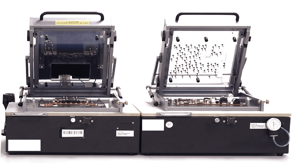
Our PCBA “bed of nails” test fixtures undergoing F.A.T. (Factory Acceptance Testing) at the client’s facility.
Any device that is designed and manufactured for use in medical settings must undergo strict validation testing to gain FDA approval. Automated test systems streamline the testing process by taking measurements and storing data to compare it to acceptance standards. Whether these are met determines if a product is ready for use.

The client’s device contained six separate circuit boards that required testing. Our engineering team recognized that to minimize the enclosure’s footprint six tests could be run from three related fixtures. These fixtures are called a “bed of nails” as the circuit board sits on electrodes that contact specific parts of the board to send signals and ensure its proper response. Our team’s design and positioning of the nail fixtures allowed us to test multiple boards at once in a single fixture, increasing overall test efficiency. We were able to achieve this by using the NI PXI hardware system which allows for high-speed data acquisition across multiple channels from the circuit board.


Left: The NI PXI hardware system provided the data acquisition requirements for our “bed of nails” automated test equipment.
Right: NI TestStand software running the test sequences required for the test of all six circuit boards.
Our printed circuit board assembly testing (PCBA testing) which entails a “bed of nails” style fixture required three integrated parts to make a solution. They were the physical fixture, the PXI hardware required for acquiring signals from the board, and the software that ran the sequence of the test. Our development team was able to use NI TestStand to program the testing sequences required for the multiple circuit boards our enclosures housed. TestStand was able to help us achieve this through its robust logic, looping, and error handling system as well as it gave us reports on the performance of the circuit boards during all tests.
Overcoming the Obstacles
The largest obstacle our team faced was building an enclosure for the testing of our client’s circuit board with wireless capabilities. The board that enabled the wireless communication of our client’s device allowed for patient readings to be transferred wirelessly, but only when the receiving tablet/laptop was within inches of the client’s device. This ensured the security of the patient’s medical information. Testing the circuit board’s wireless capabilities required simulating connectivity at different distances. As well, it was critical for our team to empirically trace the test’s results and conduct the test in a special enclosure that isolated the board from all outside radio frequencies (RF).
Our engineering team began with an RF Faraday enclosure that isolated the board undergoing testing from all radio frequency interference. We ran the circuit board through several power modes using a 3-bit signal which we used to measure the power the board was emitting at different frequencies. We did this through a digital signal attenuator which measured signals in the ISM Band – industrial scientific and medical band, a non-regulated frequency band, at 838 MHz and 916 MHz. This was to ensure our test controls locked signals with the client’s board and that the board’s signal quality was validated at several distances. To help our client’s device meet FDA certification, all tests of the board’s wireless capabilities were empirically measured and stored for validation of the data.


The vital signs monitor wirelessly interfacing with a hospital laptop.
Delivering the Outcome
Overall, our engineering team was able to deliver a full turnkey solution of two PCBA test enclosures and a final assembly test for our client’s medical device. This was done by integrating NI PXI hardware and NI TestStand software into a system that automated the procedural sequence of testing several circuit boards at once. In collaboration with the client, we were able to achieve a design iteration that best tested multiple circuit boards simultaneously and came in under budget. In delivering the customer an automated test solution capable of validating their product, we were able to provide the client with a system that validates their device’s control boards and accelerates their path to market. Our equipment is still in use by the customer today helping ensure the optimal function of their vital signs monitoring devices.
Technical Specifications
2 x RF Faraday Enclosure
2 x Programmable DC Load
1 x Digital Signal Attenuator
1 x Pressure Transducer
1 x NI PXIE 1078 Chassis
1 x NI PXIE 4113
1 x NI PXIE 4112
1 x NI PXI 2564
1 x NI PXI 8432
1 x NI PXI 6229
1 x NI PXI 2534
2 x db15 Cable
1 x db 25 Cable
1 x db 37 Cable
1 x rj 50 Cable
PCBACheck™
Businesses depend on Cyth Systems' expertise in functional test fixtures. Functional testing involves applying full operational power to a printed circuit board (PCBA) to ensure it performs its designated functions. This type of test often requires custom-built test equipment and fixtures. Cyth Systems provides support for all types of functional test strategies.
Do you need a PCB Tester?
Check our PCB Test Solution
Comments