New End-of-Line Test Bench for Hybrid Inverters Using NI Hardware
- Cyth Systems
- Apr 28, 2023
- 3 min read
Updated: Mar 27, 2024
Be*As Featured on NI.com
Original Authors: Alessandro Andreoli, Loccioni
Edited by Cyth Systems

The Challenge
Creating a test bench for the end-of-line test of Magneti Marelli inverters for the new LaFerrari car hybrid application.
The Solution
Using the NI platform, including NI PXI hardware, NI LabVIEW system design software, and NI TestStand test management software, to standardize testing the inverter unit.
Development History
Magneti Marelli required developed a new automotive hybrid inverter to be installed in the new LaFerrari car. They approached us regarding an automated testing solution. The test fixture needed to test inverter functionality and stand-alone subcomponents of the inverter. We started an R&D project in collaboration with Magneti Marelli and the University of Naples Federico II to define the test specifications for the new inverter. One University of Naples engineering student worked on the project for six months and used it as a starting point for his final thesis. The biggest task in this phase was to identify how to manage and test electric components that work with high voltages (600 V) and high current levels (800 A).
Left: Communication Connection, Right: Inverter Connection
End-of-Line Test Bench for a Hybrid Inverter
To completely test the inverter, we worked with Magneti Marelli to divide the test into the following main parts:
Unit under test (UUT) communications test—The bench powers the inverter CPU and verifies that the correct communication is occurring with the UUT. In this phase, some preliminary tests are performed, too. Communication with the UUT is facilitated using the controller area network (CAN) bus.
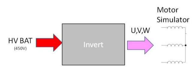
Inverter functional test—We connect the inverter to a high-voltage battery simulation (450 V) to analyze the output on the U, V, and W components. We connect the U, V, and W outputs of the inverter to an inductive load that simulates the motor connected to the UUT in normal conditions. This test also confirms that the UUT internal current measuring devices work as expected under different conditions.
Overvoltage inverter functional test—We increase the UUT’s high-voltage (HV) battery input to verify that at 475 V, the UUT generates a fault.
Undervoltage inverter functional test—We decrease the HV battery input of the UUT to verify that at 230 V, the UUT generates a fault.
DC/DC functional test—We verify that the UUT can convert the DC voltage as required. We connect the inverter HV input to 450 V and we check that the DC output voltage levels are within the specified limits. In this test, we also verify the buck-boost converter functions.
Overvoltage DC/DC test—We increase the HV input of the UUT to verify that at 475 V, the UUT generates a fault.
Undervoltage DC/DC functional test—We decrease the HV input of the UUT to verify that at 230 V, the UUT generates a fault.

For the main PC, we equipped a standard industrial PC with an MXI bus extension that helps the user remotely control a PXI chassis and installed the following items:
NI PXI-2567 | 64-channel External Relay Driver Modules |
NI PXI-6704 | Analog Output Modules |
NI PXI-6143 | Simultaneous Sampling Multifunction DAQ module |
CAN Interface | Communication Protocol |
NI PXI-GPIB | GPIB controller |
NI PXI-8430 | 8-port serial interface |
NI PXI-7841R | Multifunction RIO module |
Test Station
We mounted the UUT on a specific pallet that helps the user mechanically adapt the bench to the different kinds of inverters produced. The pallets powered the transportation of the UUT between the end-of-line bench and the other test stations in the customer production line.
Software Configuration
We developed all the software internally to manage the bench described above and have better coding and more reliable software. Our software department divided the software into different modules. The main modules we developed were the automation module and the test module. To develop the inverter machine software, we started with a previous version of a Loccioni software solution that was used to test the electronic control units (ECUs) and infotainment products.
The automation module automated the management of the bench. This software comprised a user interface and a software PLC that managed all the activities of the bench. Submodules that managed different tasks such as user identification, alarm management, and utilities composed the software PLC. We used LabVIEW to write all the modules.
The test module created and executed the different steps necessary for a complete test sequence. To give the customer the most flexibility to create different sequences, our software department used NI TestStand as the test sequencer. We customized the NI TestStand environment by adding a step that allowed for the control of specific instruments. Each instrument had its own steps that were not connected with the others, which helped us to achieve better code reliability and maintainability and to preserve the concept of modularity in the development of the custom step type. We also developed some high-level steps that contained more single commands to optimize the test cycle time.
We used TCP/IP sockets for the internal communication between the automation module and the test module because it was easy to maintain a separation between the different software modules. Using NI TestStand as the test sequencer helped us easily expand the software for additional test stations.
Original Authors:
Alessandro Andreoli, Loccioni
Edited by Cyth Systems


Comments